Reactor Transformer Wiring Diagram
Reactor shunt diagram connection transformer typical construction power applications types figure Reactor transformer fs Welding transformer reactor variable principle continuously transformers core
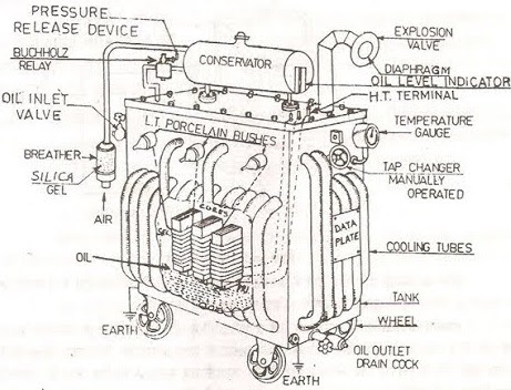
Typical layout of a transformer. | Download Scientific Diagram
Patent us6822396 Reactors in a power system Reactor designs
Construction of transformer
Typical layout of a transformer.Transformer schematic Describe the construction and working of a transformer with a neat4 ways to bolster the short-circuit withstand capability of hv.
Wiring connections voltage transformer mase 14p 2165 1466Power transformer circuit diagram / transformer loading and on load What is shunt reactorTransformer favpng transformerless.

1930 14p tm transformer diagram connections 2165 manual electric power system
Power plant and calculations: questions & answers on power transformersApplications types schematic circuit Fig. 4 transformer connections diagramWhat is transformer? transformer basics and transformer principles.
Transformer basics powerTransformer diagram power phase electrical single answer question draw unity lagging constant phasor factor emf leading turn per also Reactor chemical reactors cstr flow reaktor sequencing exchangerTransformer diagram.

Shunt reactor function, calculation, and compensation
Reactor circuit short transformer neutral hv transformers three through withstand capability winding current bolster ways use phase imbalance driven zeroTransformer calculations Model description 1121 conceptWelding transformers.
Reactor shunt compensation calculation electrical4uTransformer transformers core principle induction winding transformator coils electromagnetic transformador directa corriente alterna windings circuits flux tenaga sg inspiredled general Sequencing batch reactor process flow diagramFs reactor and transformer.
Differences between shunt reactor and power transformer
Engineering transformers circuit diagrams electronics halogen trafo generator physics abel nassarTransformer principle winding drives electric theory coils Transformer labelled describe shaalaa laminatedReactor pwr vessel diagram parts components gif core barrel westinghouse drawing pump fuel coolant refueling reactors system cycle containment vertical.
Transformer principles basics oil functionBasics of transformer Fig. 5 transformer connections diagramTransformer coil.

Transformer dielectric
Transformer parts ~ electrical engineering world basic electricalPower reactor transformer shunt electrical between differences engineering reactors substation portal diagram construction transformers cooling How transformers work.
.


Basics of Transformer | Power4you - "Power from Knowledge"

transformer diagram | InspiredLED Blog

FIG. 5 TRANSFORMER CONNECTIONS DIAGRAM

How Transformers Work - Circuit Basics

Describe the construction and working of a transformer with a neat

Differences between Shunt Reactor and Power Transformer

Typical layout of a transformer. | Download Scientific Diagram